
《CEJ》新思路!利用原子选择性占位提高超晶格储氢合金结构稳定性
2021-05-20 16:09:50
作者:材料科学与工程 来源:材料科学与工程
分享至:


超晶格储氢合金是由[A2B4]和[AB5]亚晶格延c轴方向堆垛而成(图1(a)),兼具了AB2结构的高容量和AB5结构的高催化性能,被认为是一类极具潜力的新型稀土储氢材料。然而,该类合金复杂的堆垛模式也为其结构稳定性带来了不利影响。主要问题是[A2B4]和[AB5]亚晶格在吸/放氢过程中的异步膨胀/收缩,会引起界面产生大量微应变(图1(b)),从而导致合金结构稳定性急剧下降。
为此,燕山大学韩树民教授课题组展开了大量研究工作,提出了超晶格储氢合金结构衰减机理和结构稳定性的系列理论。在课题组前期工作(Journal of PowerSources 300 (2015) 77-86)基础上,课题组研究发现,在超晶格储氢合金中,[A2B4]亚晶格体积大于[AB5]亚晶格体积,在吸氢过程中,[A2B4]亚晶格在较低压力下先于[AB5]吸氢,放氢反之。这种非同步吸放氢导致了两个亚晶格体积膨胀收缩的不一致,使得其连接界面产生大量应力引起合金超堆垛结构的破坏。课题组利用小原子半径稀土元素部分取代La选择性占位在[A2B4]亚晶格中(图1(d)),通过减小[LaMgNi4]亚晶格体积实现了减小[A2B4]和[AB5]亚晶格异步膨胀/收缩,显著提高了储氢合金的循环寿命,为调控超晶格储氢合金结构提供了新思路和新策略。
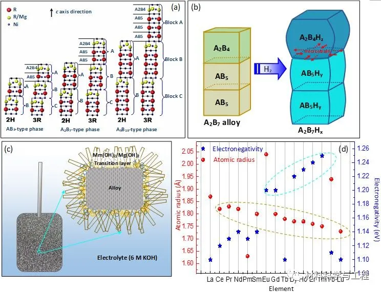
Fig. 1 Stacking structures of superlattice phases (a), microstrain caused by differentvolume expansion between [A2B4]and [AB5] subunits (b), scheme ofoxidation/corrosion during battery cycling (c)and atomic radii and electronegativity of different rare-earth elements (d).
近期,课题组通过第一性原理理论计算(图2)和结构性能实验(图3-9)进一步验证了上述研究结果,相关研究成果以题为A new strategy for enhancing thecycling stability of superlattice hydrogen storage alloys的研究论文发表在ChemicalEngineering Journal期刊。扬州大学刘晶晶副教授为第一作者,燕山大学韩树民教授为通讯作者。
论文链接:
https://www.sciencedirect.com/science/article/pii/S1385894721009839
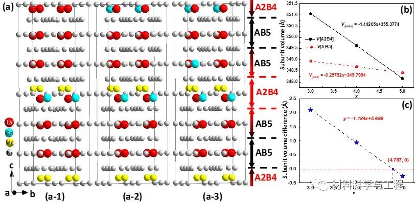
Fig. 2 Simulating models (a1–a3), changing trend of [A2B4]and [AB5] subunit volumes (b)and their difference (c) withincreasing Gd content.
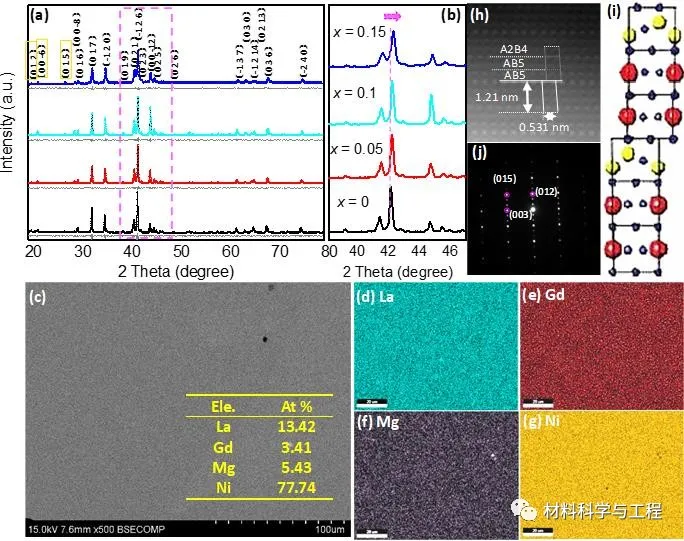
Fig. 3 XRDpatterns in the 2theta range of 20–80 degree (a) and 39–47 degree (b) ofthe La0.75?xGdxMg0.25Ni3.5(x = 0, 0.05, 0.1, 0.15) alloys, SEMimage (c), EDS mappings (d)–(g), HR TEM image (h), stacking mode (i) and SAED pattern (j) of the La0.6Gd0.15Mg0.25Ni3.5alloy.
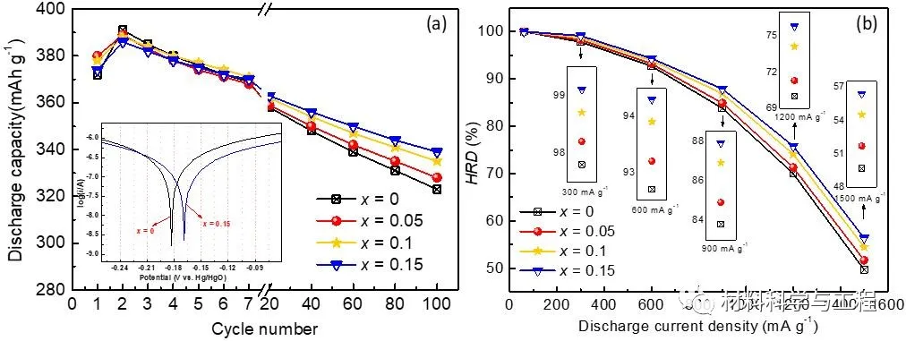
Fig. 4 Discharge capacity plots within 100 cycles (a)and HRD plots at differentdischarge current densities (b) ofLa0.75?xGdxMg0.25Ni3.5(x = 0, 0.05, 0.1 and 0.15) alloyelectrodes.
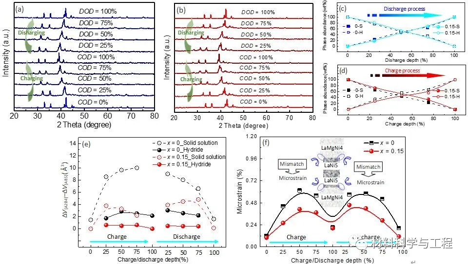
Fig. 5XRD patterns at of x= 0 (a) and x = 0.15 (b) alloys,H-solid solution and hydride phase abundance (c), volume difference between [A2B4] and [AB5]subunits (d) and microstrain in thealloys (e) at differentcharge/discharge stages.
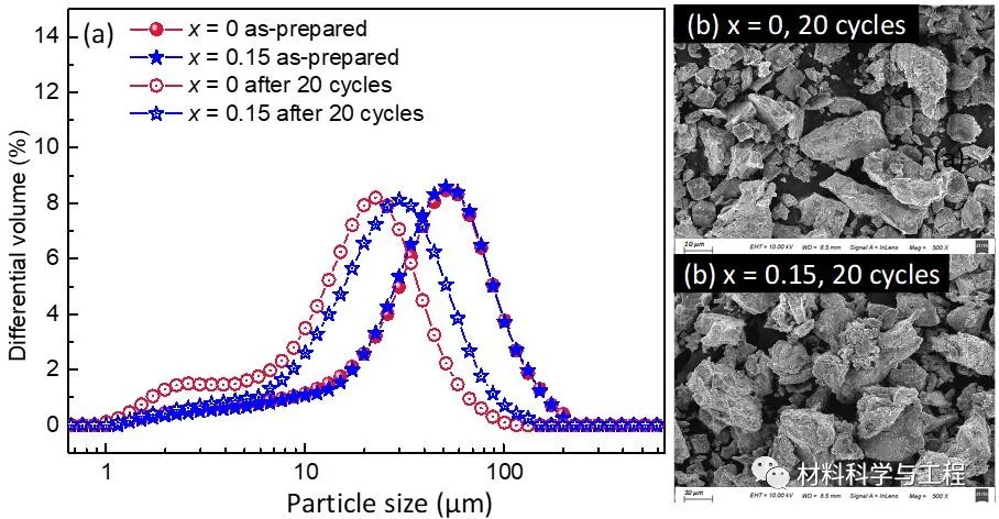
Fig. 6Particle size distribution curves of the x= 0 and x = 0.15 alloy powder beforeand after cycling (a), and SEMimages of x = 0 (b) and x = 0.15 (b) alloy particles after 20 cycles.
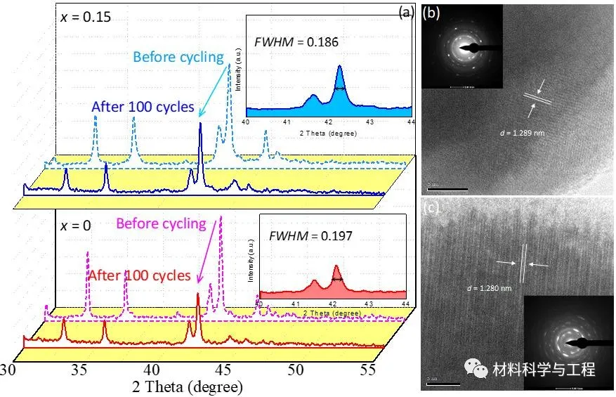
Fig. 7XRD patterns of the x = 0 and x = 0.15 alloy powder (a) and HR-TEM images of x = 0 (b) and x = 0.15 alloyparticles (b) after 100 cycles.
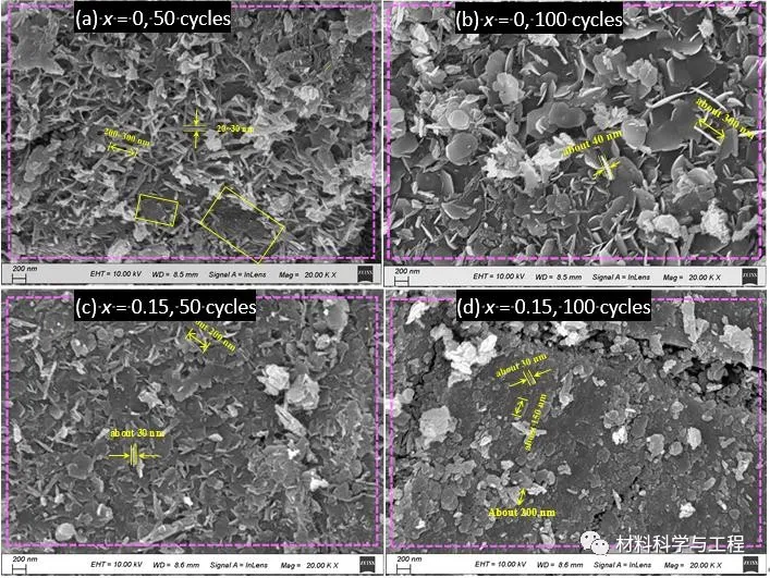
Fig. 8SEM images of the x = 0 alloy after50 (a) and 100 (b) cycles and x = 0.15alloy after 50 (c) and 100 (d) cycles.
免责声明:本网站所转载的文字、图片与视频资料版权归原创作者所有,如果涉及侵权,请第一时间联系本网删除。
相关文章

官方微信
《中国腐蚀与防护网电子期刊》征订启事
- 投稿联系:编辑部
- 电话:010-62316606-806
- 邮箱:fsfhzy666@163.com
- 中国腐蚀与防护网官方QQ群:140808414
点击排行
PPT新闻

“海洋金属”——钛合金在舰船的
点击数:7130
腐蚀与“海上丝绸之路”
点击数:5741