
香港城大《Acta Materialia》:新突破!通过触发元素晶界异常偏析成功克服合金的氢脆行为
2022-10-08 15:59:14
作者:材料学网 来源:材料学网
分享至:


一个多世纪前,普遍存在的元素氢被发现对许多金属材料有害,因为它会导致机械性能的严重降低,例如延展性、韧性和疲劳寿命,即氢脆(HE)。因此,HE在许多工业应用中都是一个关键问题,并吸引了广泛的研究。最近,利用低温转移原子探针层析技术表征氢在金属材料中的分布已取得进展。它证实了多晶合金中不可避免地存在的晶界(GBs)是氢积聚的优先位置,因为它们具有高过量自由体积。高浓度的H原子通过增强应变局部化、稳定空位、加速空穴萌生和聚结来加速GBs的脱粘,最终导致塑性有限的脆性晶间裂纹。因此,GBs对于多晶材料的抗氢脆能力起到至关重要的作用。
值得注意的是,GBs的化学环境会严重影响多晶材料的抗断裂性能。近年来,高/中熵(HEA/MEA)合金引起了相当大的关注。HEAs/MEA的成分复杂性为调节GBs的局部化学环境和HE抗性提供了广阔的空间。多项研究表明,面心立方(fcc)HEAs/MEA,如CoNiV、CoCrFeNiMn和FeCoCrNi合金,比某些商业合金,如奥氏体304不锈钢(SS)更耐HE。HEAs/MEA的优异抗氢脆能力可能归因于其低氢扩散率、高断裂自由能和低不稳定层错能量等因素。然而,尽管由于MEAs/HEAs的多组分特征,GB附近的化学分离经常发生,但很少有人研究GBs的局部化学对MEAs/HEAs耐HE性的影响。例如,据报道,镍和锰可以在等原子CoCrFeNiMn HEA中以一般高角度共分离GBs,这可能会极大地影响它们的抗氢脆能力,但它们之间的相互作用和内在机制一直没有得到很好的研究。
为此,香港城市大学材料科学与工程系杨涛教授领衔的研究团队在其最新的研究成果中成功地揭示了FeCrNiCr高熵合金中抑制其氢脆行为的关键因素。研究发现,通过控制Fe元素地添加可以非常有效地触发Cr元素在晶界(GBs)的局部偏析,从而可以有效消除Fex(CrCoNi)1-x面心立方(fcc)高熵合金(HEA)中长期存在的氢脆问题。结果表明,将Fe浓度从2.5增加到25 at.%导致HE阻力大幅提高,即延性损失从70%降至6%。同时,断裂模式由沿晶断裂转变为穿晶断裂。多尺度显微结构分析表明,Fe2.5Cr32.5Co32.5Ni32.5和Fe25Cr25Co25Ni25合金在相结构、晶粒尺寸和晶界(GB)特征方面的差异可以忽略不计。然而,非常有趣的是,近原子分辨率元素映射显示,Fe浓度的增加促进了GBs处的纳米级Cr偏析,这主要是由Cr和Fe之间的强斥力和Cr的低自结合能引起的。这种Cr元素的异常界面偏析以前在Fe25Cr25Co25Ni25合金中没有报道过,有助于增强GBs的内聚强度,并抑制GBs因GB能量减少而产生的局部氢偏析,从而导致显著的HE抗性。这些发现揭示了当前FeCrCoNi型HEA中HE抗性大幅提高的根源,同时,为未来开发新型高性能结构合金提供了新的见解,该合金对氢致损伤具有非凡的免疫力。相关成果以“Defeating hydrogen-induced grain-boundary embrittlement via triggering unusual interfacial segregation in FeCrCoNi-type high-entropy alloys”为题,于2022年10月2日发表在国际知名材料期刊《Acta Materialia》上。
该论文的第一作者为香港城市大学材料科学与工程系的李倩。 其他主要合作者包括美国田纳西大学的P.K. Liaw教授,哈尔滨工业大学(深圳)W.H. Liu教授 (共同通讯),香港城市大学S.J. Zhao教授(共同通讯);哈尔滨工业大学(深圳)Y.L. Zhao教授等。该研究受到了香港研究资助局(NSFC),国家自然科学基金(NSFC)、广东省科技厅等项目的支持。
论文链接:https://doi.org/10.1016/j.actamat.2022.118410 。
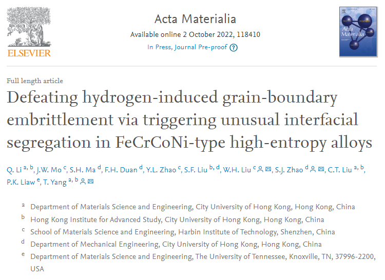
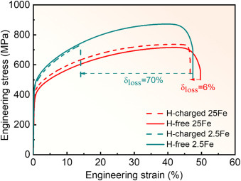
Fig.1. Engineering stress-strain curves of the 2.5Fe and 25Fe alloys in the hydrogen (H)-charged and -free states.
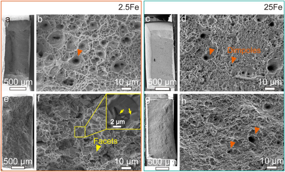
Fig. 3. Fracture surfaces of (a, b, e, and f) the 2.5Fe and (c, d, g, and h) 25Fe alloys in (a-d) the H-free and (e-h) H-charged states. The H-charged 2.5Fe alloy shows an intergranular fracture morphology with facets (marked with yellow triangles). Grain-boundary triple junctions (marked with yellow arrows) can be clearly observed on the magnification image (the top-right inset) of the region in the yellow box. The H-charged 25Fe samples show ductile fracture morphologies with typical dimples (marked with orange triangles).
Fig. 4. Microstructures of the as-annealed 2.5Fe and 25Fe alloys. (a) X-ray patterns of the H-free/-charged 2.5Fe and 25Fe alloys, and inverse pole figure (IPF) maps of (b) the H-free 2.5Fe and (c) H-free 25Fe alloys showing the single fcc phase recrystallized microstructures. (d) A bright-field TEM image and (e) a high-resolution TEM image of the H-free 25Fe alloy presenting the single-fcc structure without the formation of other precipitates. (f) The EDS maps of the regions in the H-free 25Fe alloy exhibiting the homogeneous elemental distribution in the grain interior.
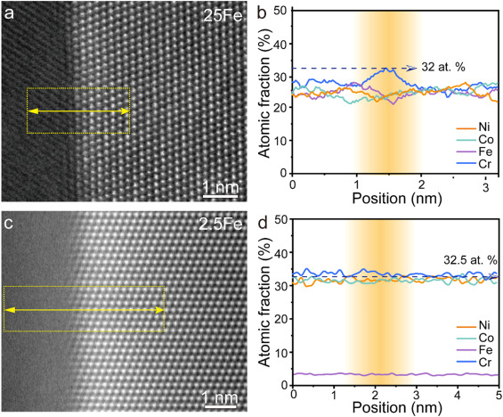
Fig. 5. High-angle annular dark-field (HAADF) images of GBs in (a) the H-free 25Fe and (c) H-free 2.5Fe alloys, and (b, d) the corresponding elements profiles across GBs.
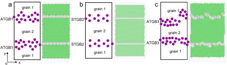
Fig. 6. Schematic of GB Structures. The GB configurations for (a) the GB1 (asymmetric tilt GB, ATGB, Σ13{320}), (b) GB2 (symmetrical tilt GB, STGB, Σ11{332}); and (c) GB3 (ATGB, Σ13{100}).
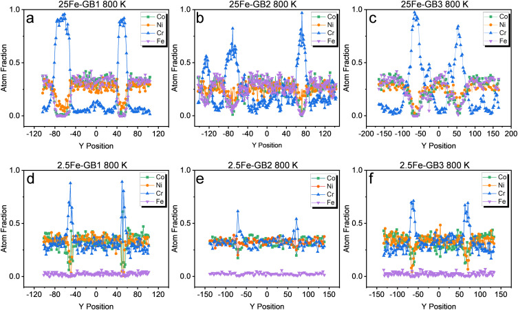
Fig. 7. The composition profiles across the computational systems along the Y direction after MC/MD at 800K for (a, d) GB1, (b, c) GB2, and (c, f) GB3 in (a-c) the 25Fe and (d-f) 2.5Fe alloys.
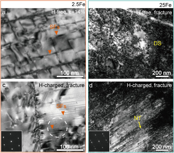
Fig. 11. Typical bright-field TEM images of (a) the H-free and (c) H-charged 2.5Fe alloy deformed with the engineering strain of ε = 14% (the H-charged 2.5Fe alloy failed at the strain ε = 14%); and the fractured microstructure of the 25Fe alloy (b) without and with (d) hydrogen charging. (DS: Dislocation structure, NT: Nanotwin, SFs: Stacking faults)
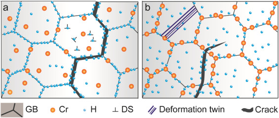
Fig. 12. Schematics illustrating the HE mechanism of (a) the 2.5Fe and (b) the 25Fe alloys.
免责声明:本网站所转载的文字、图片与视频资料版权归原创作者所有,如果涉及侵权,请第一时间联系本网删除。
相关文章

官方微信
《腐蚀与防护网电子期刊》征订启事
- 投稿联系:编辑部
- 电话:010-62316606-806
- 邮箱:fsfhzy666@163.com
- 腐蚀与防护网官方QQ群:140808414
点击排行
PPT新闻
“海洋金属”——钛合金在舰船的
点击数:8188
腐蚀与“海上丝绸之路”
点击数:6503